Install Painted Valve Covers
Tools you will need:
Expect approximately 1-2 days install time
* Color of your choice ** You can pick up some Simple Green or other cleaning agent from your local PepBoys or Wal-Mart. |
Date:
June 3, 2000 Car: 1998 Pontiac Trans AM Installers: Bryan Heusmann Email: nvehtis@nvethis.d2g.com People who helped me from major tech
|
Legal Notice
***I am not responsible for anything that happens to you or your car from here on out. This is for information use only and you do so at your own risk***
When purchasing, viewing, using, and/or any
other method applied to this publication you agree to the following statements.
You, your next of kin, heirs or assigns release www.installuniversity.com,
all other persons associated in the making, production, participation, and sale
of this publication. Rephrased in plain English: When you purchase
this CD, book, or view this web page you, your next of kin, heirs or assigns
agree not to sue any associated persons with the publication for any accident or
damage in ANY form (mental or physical to your car and/or yourself) because of
this publication or your failure to heed proper safety, maintenance and/or
modification procedures. You also agree that your next of kin, heirs
or assigns cannot sue all persons associated in the making, production,
participation, and sale of this publication.
I do not know the names of all the parts so there might be some non-technical references throughout this document. This should be a straight forward install that should take you a few hours:
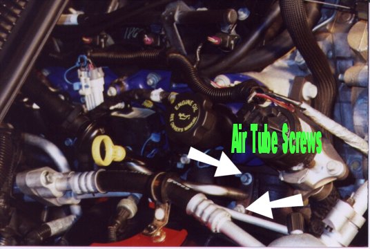
1. First what you want to do is remove the air hose. You want to remove the two (2) 10mm screws that connect it to the Headers. (See Figure 1)
Note: DO NOT LOOSE THE GASKET BETWEEN THE EXHAUST MANIFOLD AND THE AIR TUBE!You will need to replace this when you are finished. If you do not put this gasket back in place there will be a loud knocking noise under load. The replacement part # is-12553617
2. Next you want to remove the tab at the other end that holds the rubber tube on. You can use a flat screwdriver or a fingernail to remove the clip. Slide the clip up the rubber tube a bit and pull on the metal part to disconnect it from the rubber tube. When is is off just set it aside. Now that you have removed the air tube it is much easier to get to the coil packs. You will need to remove the coil packs. This will make it easier to remove the valve covers.
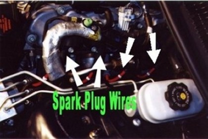
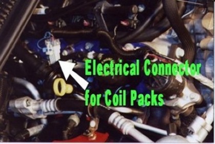
3. To remove the coil packs, first remove the spark plug wires from the packs. (See Figure 2)Then disconnect the large electrical connector. (See Figure 3)Next you want to remove the 10 mm screws that hold the packs to the valve covers.
Note: On 1999-2000 vehicles you must remove the whole coil rail. The 1998 vehicles are individually attached to the valve covers. After these screws are removed the coil packs should lift off.
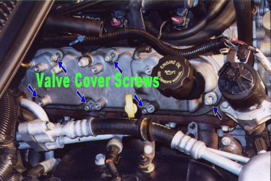
4. Once you have the coil packs off, set them aside. Next we will be removing the valve covers. You will need to loosen the nine (9) 10 mm screws (See Figure 4)that hold the valve covers down. You might hear a hissing air noise as you move around the cover. Don't worry, this is just air that is escaping from the covers.
Note: On the drivers side it may be a little hard because of the fuel line. I did not disconnect the fuel line, but slid the drivers side valve cover off under it. It was a little difficult but it just fit. I do not know how to disconnect the fuel line so I will not go into detail here. If you are experienced and know what you are doing, then you do so at your own risk.
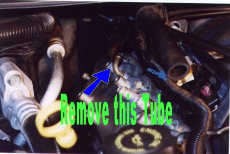
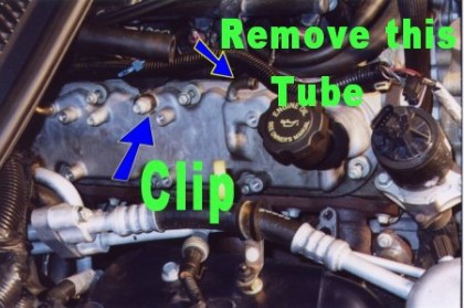
5. Before lifting off the valve covers you will need to disconnect some rubber tubes from them. On the passenger side remove these tubes (See Figure 5).Also on the passenger side you will need to remove this clip. (See Figure 6)On the drivers side the only thing that needs to be disconnected is the tube in the back. The "L" shaped rubber tube in the back will take a little elbow-grease to remove. Just keep tugging at it 'till it comes off.
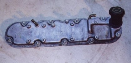
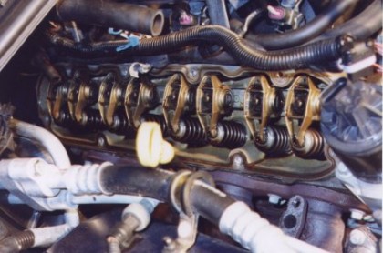
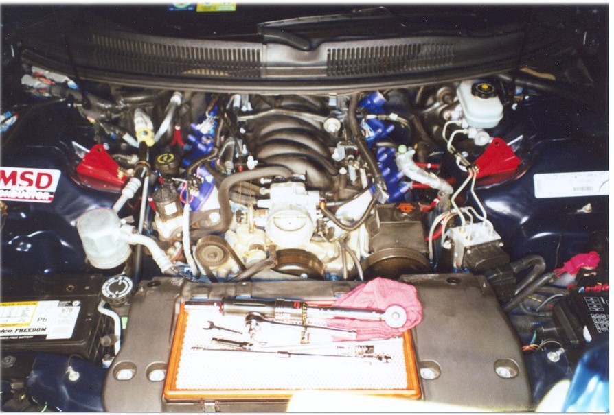
6. Now that you have the rubber tubes disconnected, carefully lift off the valve covers. You should have something in your hand that looks like this (See Figure 7)and your engine bay should look like this (See Figure 8)
7. Now is the easy part. I do not know how to take off the oil filler neck or the plastic tube connector (very technical term there) on the drivers side cover. What I did was cover them with painters tape. I also covered the tube heads on the passenger side cover with painters tape also.
8. Lay the valve covers on something that you can get paint on. I used a flat piece of plywood. First I took a small piece of 200 grit sand paper and ran it over the covers lightly. You might want to remove the screws unless you want them to be painted with the rest of the covers. To remove them slip a flat head screwdriver under the rubber washer thing and pry it out. Do that for the rest of them. I washed the covers with some warm water and some degreasing detergent that I picked up at my local PepBoys. After doing that and air-drying them for about an hour, I applied 6 coats of high temp (1200o) engine paint. I let them dry for about 30 min. between each coat. Then I applied about 3 coats of high temp (500o) engine enamel letting them dry for about 30 min. between each coat of that. The paint I bought wasn't glossy so that is why I applied the engine enamel. After you have them painted to your liking it is time to assemble everything back together.
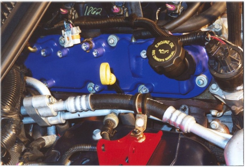
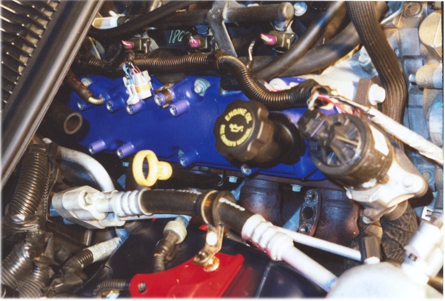
9. We are pretty much going to do everything backwards now. Replace the rubber washers, with the valve screws you took out, back in their holes. Just press them back in. What you want to do now is lay the valve covers on the valves, making sure the rubber gasket is in place (This may slip out and should just be edged into place until is sits properly). Now you can center the covers and begin to tighten the screws down. I talked to a service technician at my local dealer cause I did not know what to torque the screws to. He looked it up for me and said the valve cover screws should be tightened to 12 NM. That didn't quite feel tight enough for me so I gave it another 1/2 turn. It should look something like this. (See Figure 9)
10. Now you have to re-attach the clip that came off of the passenger side cover. After that re-attach the two (2) tubes that you removed from the passenger side valve cover. Then attach the "L" shaped tube to the rubber tube on the drivers side. Once you get all that done you should just have to replace the coil packs and/or coil rail and plug wires.
11. Ok, to do that you want to lay the coil packs on the painted valve covers and get the screws in lightly so you can still adjust them. I attached one (1) 10 mm screw on the top part of each coil pack (top portion only), and then adjusted them in place. After they were positioned correctly I tightened them down with the rest of the screws. The coil packs should be tightened to 106 in.-lb. of torque. After you have the coil packs in place you can connect the spark plug wires back to them.
12. Ok, this is the home stretch. The only thing left to do is to reattach the air tube on each side. To do this, you want to push the one end into the rubber tube that you disconnected it from. Slide the clip over the lip and press it together until it is tight. Then you want to attach the other end to the area on the headers. (See Figure 10)
Figure 10
Note: DO NOT FORGET TO PLACE THE GASKET BETWEEN THE AIR TUBE AND EXHAUST MANIFOLD!
You will need to replace this when you are finished. If you do not put this gasket back in place there will be a loud knocking noise under load. If you happen to loose it the replacement part # is-12553617
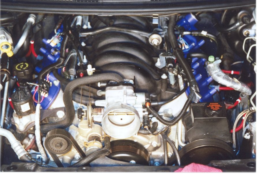
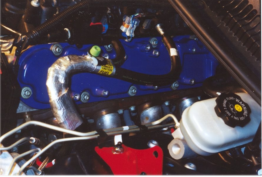
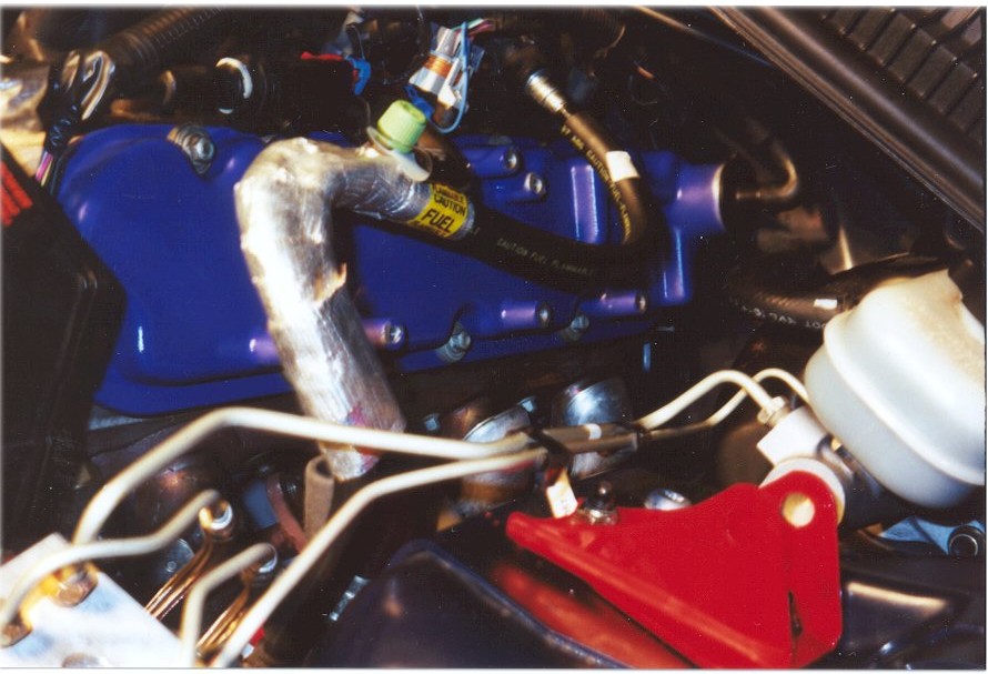
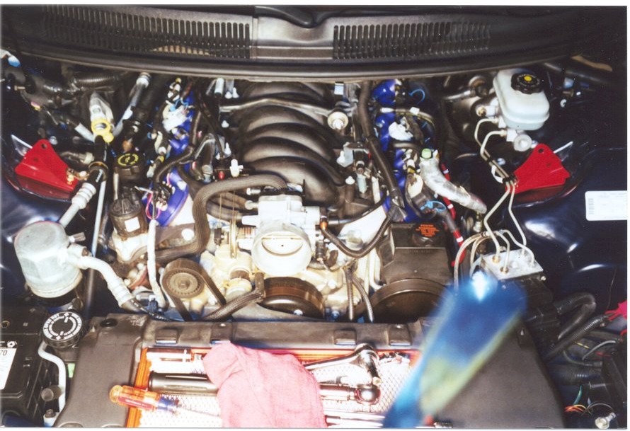
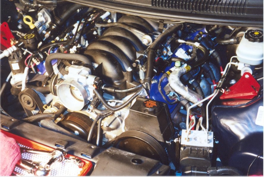
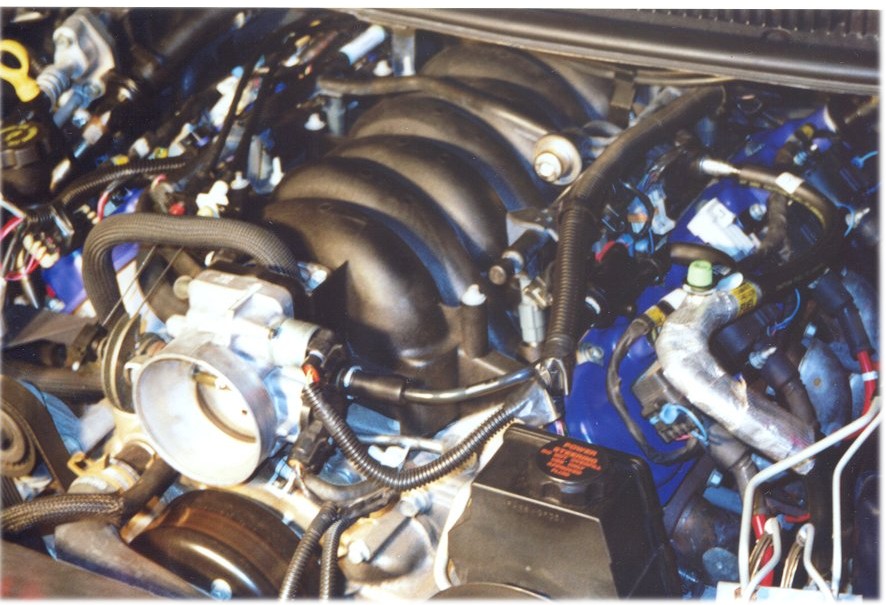
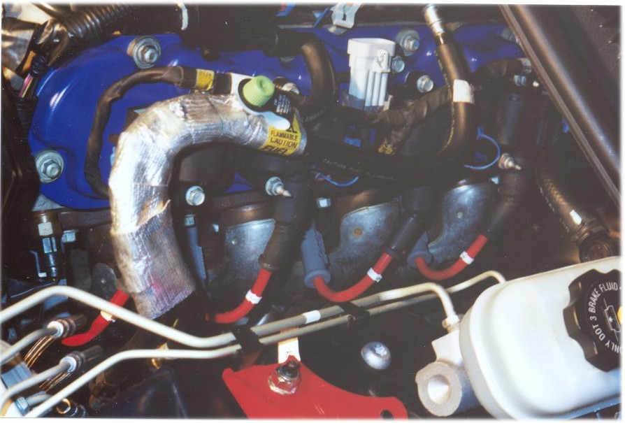
13.The two (2) screws should be tightened to 180 in.-lb. or 15 ft.-lb. I believe that this should be the last step. If you have anything left over, then take a step back and retrace your steps. You should have something that looks like this (see pictures below).
| Click on pictures for a Larger image | ||||
|
||||
|
||||
|
|
|
||
|
||||
Before |
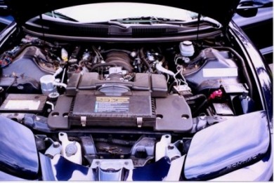
|
After |
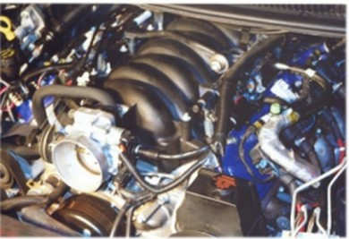
|